Pie-Stop for Pi-Hole


Just setup a pi-hole for DNS filtering. I subscribed to a bunch of block lists and then subsequently prevented Christine from loading a site on her work laptop. Seeing as how the network admin is not always home to take care of issues like this, I wanted a way for anyone in the house to disable filtering for ~5 min. There are many, many, many IoT button tutorials out there, with lots of different hardware, so this post will cover light details, please use it for inspiration.

If you haven’t done any work with the ESP-01S modules – these are the tiny 2 GPIO pin ESP8266 boards that have 8-pins, deep sleep mode, and can run off a 3.6V Lithium 18650 for months. I highly suggest getting a “code burner” board from the Jungle Site. This just makes de-bug and programming with Arduino IDE quality of life 1000% better.

The code required is going to change, and I’m not maintaining C# for this one, but it works like so: You need to connect to your WiFi, it needs to send a web GET request to your pi-hole, and then it needs to go into deep sleep. Something like: “http.begin(wifiClient, “http://your_pie_ip:80/admin/api.php?disable=300&auth=”);” and then “ESP.deepSleep(0);” This means the device is always powered and runs the code on startup.

The button is tied to the reset pin like this. I had to find a NO (Normally Open) e-stop button to get this to work. There are tutorials out there on how to switch this for a NC (Normally Closed) e-stop in case a transistor is easier / cheaper to get. I whipped up a 3D enclosure to hold all of this and posted it over on Printables.com. Lots of other models there if this one doesn’t satisfy your needs. Printed the bottom in clear PETG.

  • 3D Printed Enclosure
  • ESP-01 Code Burner
  • ESP-01S or regular ESP8266 module
  • E-Stop button (Normally Open)
  • Lithium Battery Charger Module
  • 18650 battery + holder
  • Wire + 10K Ohm resistor


The Common Tool Set

Quick post to chat about tools: As a collector of them, and as a maker and hacker, I find that I have boxes of very specific tools for very specific applications. I have wood working tools; Mechanics tools for working on cars; Plumbing tools; Car electrical specific tools; Soldering and circuit board electrical; Watch repair; Sewing; etc. It’s nice to have a single box of tools that you can haul out for a very specific need. To say: “Here is everything I need for THIS job.” It’s very satisfying.

This helps tame the garage, workshop, and study. You no longer have a big shelf filled up with everything from a circular saw to AA brass tweezers. You can put the pipe cutter, flux, and fittings away in a box marked “PLUMBING” until needed. You don’t have to dig through a pile of electrical crimpers to get the coaxial ones you need for AV work.

Sometimes though, projects require a common tool set. I went to hang a picture in my office and I had 5 hammers to choose from. I fixed the fan in our bedroom and I had to go into 3 different places to get a set of wire strippers, a long screwdriver, a pair of pliers, and some super glue. I found myself leaving my watch repair box open all the time for access to a good pair of tweezers and a loupe. My electronics box is more like a remote soldering station and I found I would also leave it open on the counter for access to 2 long screwdrivers, a pair of flush cutters, and a pair of wire strippers.

“I leave this open on the counter all the time for 3 tools,” I thought. Then I looked at the watch repair box, also open for access to 2 or 3 tools. 90% of the time I go into the garage it’s to get a pair of pliers or a screw driver. “Yeah, I can fix this.”

Here is my common tool set. This represents the tools I use 90% of the time. Put one together for yourself and stop 15 trips to 3 places to finish a project. I on-purpose didn’t put links, because I don’t want to update them, and I don’t monetize this site. Take that as an honest recommendation.

  • Sharpies (regular / fine)
  • Leatherman Style PS
  • AA Tweezers (and small tools)
  • Wera Kraftform Kompakt (screw driver with bits)
  • CRKT Drifter (folding knife)
  • EXTECH EX330 Multi-meter (with box of extras)
  • 1lb Brass Hammer
  • Wiha precision screwdrivers
  • AA LED Flashlight
  • Klein Tools Scissors
  • Wire strippers
  • Flush cutters
  • KNIPEX Cobra self locking pliers

It’s okay to shower with your dive watch.

ESP 01 + BMP280 Dead bug

There’s a fable I once heard on a forum…Reddit – or was it YouTube? – about not showering with your watch. Obviously we’re talking about a water “resistant” watch – with a “dive rating” of 30 meters or more. It goes something like: “The water pressure from the shower falling a few feet is enough to push past the seals.” Similar, I’ve also heard that while swimming: “The pressure created when you swing your arms under the water can also push a watch past its water resistant rating.” This sounds like it might have some truth to it, but we have to get a better idea of the forces acting on (and inside) your watch. Forty years ago manufacturers could say “water proof” on the dial, but that implies that water (or atmosphere) will never get into the case. Nowadays, watches have synthetic seals, are pressure tested at the factory, and are sporting ever higher depth ratings. Yet, to not mislead customers, can only say “Water Resistant”. BUT REALLY?! A 300m dive watch can’t handle a shower? Is this a myth? What’s really going on inside?

About a month ago I was working with an ESP-01 (ESP8266) board on another project and it was on my work bench next to a watch I was working on. At only 25mm long, I thought: “I wonder if this could fit into a watch case? I wonder if they make a really small pressure sensor?” A google search later and I had a BMP280 breakout from Adafruit on its way to me. This is a super accurate barometric pressure sensor that measures in Pascals. It is literally designed to help GPS calculate altitude. For reference 6,985 Pascal is equal to 1.0 Pound (of force) per Square Inch (psi) OR 1.0 lbs/in².

Can you calculate altitude with a pressure sensor? Yep! Our atmosphere doesn’t have a steady density everywhere on the planet. It changes with the weather, temperature, and how high above the ground you are relative to sea level. If you go up in altitude, there is less pressure. If you know the pressure at sea level, and the temperature, you can accurately tell your elevation. In my testing, the atmosphere at my house registered around 14.4 psi – can you figure out my elevation? Here’s a handy calculator for those wanting to learn even more about atmospheric pressure. Even with an less precise measurement like psi – you can calculate I’m around 570 feet above sea level.

Powering the ESP-01: While possible with some expensive super capacitors, the WiFi module draws too much amperage to start up with a coin cell battery. If I wanted some energy density, I was going to need a tiny LiPo battery. Adafruit to the rescue again with this 150mAh (19.75mm x 26.02mm x 3.8mm) Lithium Ion Polymer Battery.

My first build was hasty. After testing I knew I needed pull up resistors on everything to get I2C working. The 1/2 watt resistors I had were just too big to get the device into a watch case. I prototyped it all on a bread board before ordering some SMD resistors. I “dead bug” soldered 4x 3.3k/ohm resistors and my two 330 ohm 1/4 watt resistors had enough space hanging off one side of the board and sensor. For reference SCK = SCL AND SDI = SDA when looking at the BMP280.

Now that I had all the parts, the battery on top of the sensor, on top of the ESP-01 the height was pushing close to 9mm. I was initially trying to squeeze this into a Seiko SKX007 dive watch case, but even with a domed sapphire I only had around 7.5mm in height available. “We’re going to need a bigger boat  -err submarine.” Not to harp on a cliche’ stereotype, but the first manufacturer of giant dive watches that came to mind was Invicta. Don’t worry, I didn’t gut one, I found a “Grand Diver” at 46mm with no movement on eBay for $25. 🙂 Even with an external thickness of 16mm there’s only about 10mm to work with inside. The back tapers, and the crystals* are about 2mm thick each. (*Bonus diplay caseback! 😀 ) This watch lists a 300m (1000ft) dive rating. Meaning, you could slip past 60m of depth as a recreational diver and fall prey to hypoxia before water would ever push past the seals of this watch, let alone crack the crystal. 😉

Ready to dive Captain!

It was at this point I was glad this sensor package included temperature. ACROBOTIC’s video on getting sensor data from the ESP8266 and his corresponding websockets Arduino code available on GitHub made the software side (my least favorite part) pretty easy. After digging into chart.js I was actually able to add a second line graph to report temp and pressure. Testing js code INSIDE the Arduino IDE is pretty impossible, so I used jsfiddle.net to work out any syntax [programmer errors] before copying it to the IDE and flashing it to the ESP8266.

Let’s get testing!

  • First big surprise: Closing the caseback with the crown in, increased the pressure inside the case as much as 0.3 psi! That caseback and the gasket worked as a diaphragm when threaded closed.
  • Nice surprise: With this setup, I was able to detect when the crown was threaded in. This tiny 3mm cylinder of air, pushed in a few mm, was able to slightly raise the pressure in the watch.
  • How Accurate? In one instance, when pressure and temp were steady, I was able to detect that my Air Conditioning had come on. Pressurizing the air in the room slightly and thus inside the case with the crown out.
  • My tests were all done around 70F degrees ambient temp, and 14.4 psi of atmospheric pressure. The sensor measures in Celsius and Pascals – which were converted into sloppier “North American” measurements. Still accurate but less precise. 😐
  • Why precision doesn’t matter here: It takes a LOT of force to blow out a crystal or squeeze past a seal. 100 Pa won’t make a difference, 1 psi might (6.9 kPa). These are temp and pressure measurements that Americans use every day, so it’s easier to understand the effects. Consider 100m of depth is equal to 142psi and 300m of depth is a whopping 427psi.

Oh yeah, temperature affects pressure.

When I first got this prototype together, I didn’t have the temp sensor reporting. I noticed immediately that, just sitting on the desk, the pressure was rising in the case. First a few hundredths of a psi, and then almost half a psi (0.5) in a few minutes. It was increasing continuously. The only explanation for this must be that the wifi package with cpu and battery was getting hot. The only way to show this, was to report temperature along with pressure. Sure enough, my hypothesis was correct; as the electronics warmed up, the pressure went up.

Shockingly cold!


Plunging the watch with sensor package into a cup of ice water yielded some interesting results. Right off the bat the pressure plummeted, and in 32F (0C) ice water, the pressure reduced to as low as 13psi. As low pressure here is a vacuum; -1.4 psi of pressure was now sucking on those seals from inside the case. Outside temperature changes make a big difference on the pressure recorded inside the watch. Warming the watch up to 100F increased the internal pressure by as much as 3psi!

Recreational Diving

This is a pressure vessel that will safely hold 100psi of air pressure. It will help us to simulate 70m of depth into the ocean. For those interested, here is the depth calculation. 70m is 10m past where recreational divers would go, so this is a decent real world test of watch water resistance.

Pressurized, only a 0.3psi change is recorded inside! Yes, 100psi is attempting to sink into the watch, but the seals; crystals; crown; and watch case are preventing this from happening. The seals and crystals are squeezing in ever so slightly, resulting in the 0.3psi increase in pressure inside the watch. This is exactly how “dry” pressure testers work. Check out this Hodinkee article – Under Pressure: A Look At Rolex Water Resistance Testing

“The dome is sealed shut and air pressure inside the chamber is increased to the desired level, up to 10 bar, which is equivalent to about 100 meters of water pressure. As the air pressure increases, any leaks in the case will allow air to infiltrate the watch itself and deflect the crystal upwards slightly. The probe that is resting on the crystal detects this deflection and transmits a digital readout on the front of the machine, both in micrometers of deflection and a simple “Pass” or “Fail” verdict based on set criteria that differ depending on crystal type.”

Time for a shower…

Close enough to strip paint…

This is my gas powered 2800psi pressure washer way too close to a 300m dive watch. I’m using the white nozzle here to simulate a proper soak. I was only able to change the pressure inside the watch 0.14psi or about half of our 70m dive of 0.3psi. If water was somehow able to seep into the case we would have seen a much higher change in pressure, and the pressure wouldn’t revert back to where it was when we stopped hitting it with the spray. If taking more than 2000psi of shower to the case is like diving 35m, then I’m sure that your 50psi home shower will not hurt your dive watch. 😐

I tried to simulate pressure from taking an actual shower, and pressure from swinging my arm in a tub of shallow water – but nothing registered. I was excited to film some footage at the lake, but besides temperature, I couldn’t detect a pressure change at all. For reference here; 1m (3ft) of water is only 1.42psi, which is a lot less than 2000. 😉

If your seals are bad, your watch isn’t water proof… Don’t blame the shower.

Just as 100psi is kept out of the watch, -1.4psi to 3.0psi is kept inside. If your seals are bad, it will be catastrophic to jump into freezing cold water. The pressure inside the watch will fall with temperature, and actually suck water in.

I would argue that taking a shower with a watch that has bad seals is actually a tiny bit better than jumping into a cold pool. The watch warms up slightly with your hot shower and air is pushed out. Until it isn’t…

If you find yourself in this panic situation (wearing a questionably sealed vintage watch in the shower by accident). Immediately take the watch off and dry it thoroughly. Then place it in another room where it’s cool and dry. As I showed, when the watch cools off from the shower, the pressure inside will reduce and could suck in atmosphere. You don’t want this to happen in the 90% humidity from the bathroom.

But I take cold showers, and I like to ski.

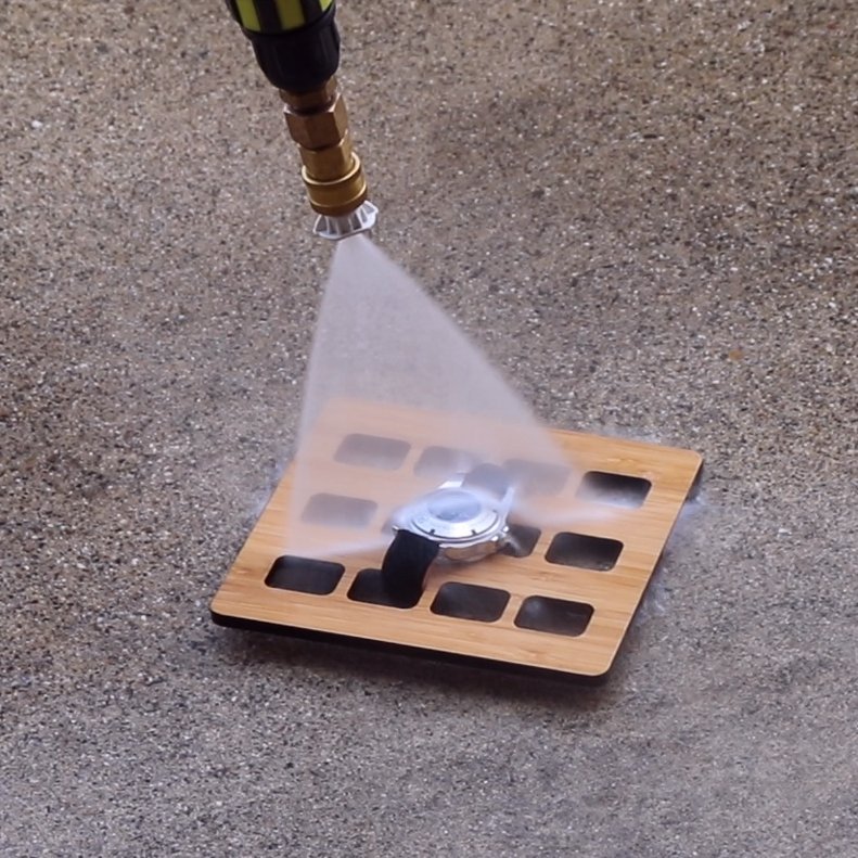
Arguably problematic is opening your watch up (unscrewing your crown) at altitude. If you’re at 10.5psi of atmosphere (9,000ft) and you head back to sea level (assuming temp on your wrist remains the same) you could have a -4psi vacuum inside the case now. Jumping into the cold shower could reduce that even more. Is that the pressure combination that pushes the seals past their limit? This now seems much more plausible than “the water hitting the case did it.”

  • Myth busted. Go back to showering with your dive watch if you want.
  • Make sure your crown is screwed in all the way. Check it before water activities.
  • Probably should avoid setting the time in extreme environments.
  • These are purpose built tool watches. The moment you second guess their ability, they become jewelry. 🙁
  • Have a watch older than 10 years that would be a shame if water got into it? Get the seals replaced and get it pressure tested.

Video:

[youtube https://youtu.be/41HYLJL1eCc]

A Better (inexpensive but completely overkill) Watch Winder

If you’ve ever heard a CNC machine or a 3D printer, you know the ‘zip, zip, ziiiiiiip’ sounds it makes are coming from the 3 stepper motors trying to keep up with the chips or hot plastic nozzle. Old hard drives were driven with full size stepper motors, and the sound is a Hollywood staple. New action movies with modern computers will still use the stepper motor sounds for the ‘computer is chugging on something’ sound effect, even though these drives are now 20 years old and computers are silent. Are modern stepper motors noisy? They certainly can be, but it turns out the driver that energizes the two coils in the motor dictates how much noise it makes.

I have been on the hunt for a ‘good value’ watch winder to keep my small collection of modified Seiko watches ready to wear (and for testing). With the requirement that I was going to keep this on a bedside table, it needed to be SILENT. Watch winders are priced at what you would expect for a luxury item that no one really needs, for mechanical watches that can cost a fortune. Good ones are really (REALLY) expensive, and cheap ones are noisy and disposable. The motor and gearing being the point of failure made me wonder about steppers as a replacement. Ziiiiiip?

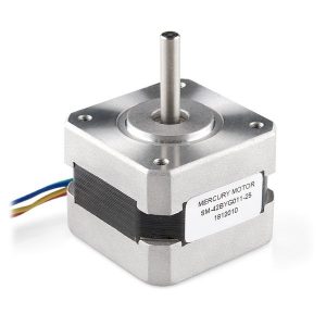
The next google search brought me to Kevin Darrah’s YouTube channel. Where he was testing out a Trinamic SilentStepStick on his 3D printed watch winder. ‘Bingo!‘ I thought, as his Hamilton spun silently around running a small program from an Arduino.  The Trinamic Stepper driver made the motor absolutely silent! But how to build the housing? Even Kevin admits that his CAD was quick and hasty for the mount, and I knew that modeling, printing, and building something like the typical spring loaded holder for the watch was going to be super time consuming and never cost less than a $350 luxury silent watch winder.

What I really needed was a good looking housing, with the cup and watch holder molded plastic, that I could replace the motor, and stuff the electronics inside. A quick Amazon search gave me lots of $40 options, and I’m sure if you were more patient, you could get something in the $25 range shipped from Asia.

I was interested in learning more about stepper motors and controllers. I had a small stack of Arduino Pro Mini clones sitting around, and the stepper motor and driver were going to cost around $30 shipped. Even with $50 of additional parts, this still put me under $100 for a precision software controlled watch winder. Plus a fun two hour hardware project to experiment with Arduino controlled steppers. 😀

Receive intact winder – proceed to tear it apart. As expected, this uses a 5V DC motor powered with a non-UL listed USB power supply. It did have a decent capacitor across the power input on the board, but I was not surprised when I plugged it in and the gear whirring from a hollow box could be heard a few feet away. I removed this and de-soldered the power junctions from the circuit board. I was able to re-use the motor connector, selector switch, and capacitor.

Two things of note: Make sure you have a capacitor across the 12v motor supply side of the SilentStepStick, and connect ALL of the grounds together – including the data side of the stepper driver. At one point, 12v was back-feeding into my 5v Arduino, and let’s not even talk about what happens when you plug that into a USB powered FTDI friend.

I completely removed the battery holder with a Dremel tool, thus giving me a little access panel to mount the Arduino Pro Mini to. A little trimming of the watch cup, some screws, and an aluminum bracket made with the help of a drill and a vise. Some hot glue to keep the bracket from shifting, and the hardware was complete.

After some setup in the Arduino IDE, I was up and stepping! You can really make this as complicated or as easy as possible. I didn’t even connect the data lines to the SilentStepStick. I’m simply using the default setup with only the ‘enable’, ‘step’, and ‘direction’ pins. This means a simple loop drives the motor, and a pin change flips the direction:

for(x= 1; x<1600; x++) //360 degrees
  {
    digitalWrite(step-pin,HIGH); //Trigger one step forward
    delay(4);
    digitalWrite(step-pin,LOW); 
    delay(4);
  }

digitalWrite(dir-pin, !digitalRead(dir-pin)); //flip direction

digitalWrite(enable-pin,LOW); //disable motor when resting

Important: Make sure to disable the motor when ‘resting’. No need to keep the stepper energized with 12v turning into heat. My stepper reached about 100F degrees sitting on my desk, and I added a digitalWrite(enable-pin,LOW); during the rest period. Now the highest temps I see are around 80F.

I timed that it makes 6 full rotations in one minute. 25 turns takes a little over 4 minutes (4.16). I then rest for 25.83 minutes (1550 seconds) and do another 25 rotations in the opposite direction. 50 turns an hour = 600 TPD (Turns Per Day). Automatic watches need between 600 – 800 TPD in order to stay wound and ready to go. I utilized the stock selector switch for ‘STOP’, ‘800 TPD’, and ‘600 TPD’ – there are some watches that only wind in one direction, so you could make any program for any number of turns and rotations. One thing I love is that is does ‘exactly’ the number of steps + turns that you specify. So if you place the watch in the 12-up position, days later it will still be in the 12-up position.

Adding a completely silent stepper motor to upgrade an inexpensive watch winder was a lot of fun, completely overkill, and still cost a fraction of a high end watch winder.

Action Video: [youtube=https://youtu.be/jh7ITYEgIQw]

Restore an old Mac

In 1995-1996 I ran a Macintosh GUI BBS on a computer I rescued from the trash. The Macintosh SE/30 was prized for its ability as a server, and at one point mine had four external SCSI drives attached to it, two Hayes Accura V.92 14.4K Modems, and the 40MB built-in drive running System 7. With the RAM maxed out to 8MB and an external monitor card, this build was a top notch machine of its day. If you’re going to restore an old 16bit PC, why not make it the last of the V8 interceptors.

Before I get too far, let me declare that this is not a “how to”. There are far more traveled forums than the comment section of planetkris, and there are many hundreds of articles, and thousands of different things to try to get your retro hardware working. Only one of which will be covered here.

In a box, in a bin, in the last three houses my parents have owned, and saved from a flood, was a couple of my old Macintosh Computers. I think I have mentioned that I would pay to ship these out to me over a dozen times in last 10 years. I have a significant pile of keyboards, mice, cables, and adapters that go along with them. In October of 2018 they arrived in the back of the car that my parents took on their post-retirement cross country trip.

Yes, of course “leaking capacitors.” 15 years of electrolytic goop has been corroding the motherboard. I powered it on anyway just to see what I had gotten myself into, and it actually booted off a floppy that I made on my Windows 10 desktop. The fact that I was able to do THAT MUCH was particularly amazing considering the hardware/software emulation chain that was taking place: Windows 10 driver to access emulated floppy over USB writing bits from a 1990’s .img file using a 32bit Macintosh floppy conversion software on a 64bit multi-core machine. I wasn’t remotely running this on a VM desktop at the time – FYI.

Restoration VS. Nostalgia: I did NOT want this build to turn into a Raspberry Pi attached to a 7″ LCD monitor grafted into the case. I get why people do that, but it’s not at all true to the design of the machine, and it really cheapens the feeling one gets when they see an old computer they used in High School or College with the side hacked open and USB hubs sticking out. I looked into driving the original monitor with a Pi, and it has been done, but emulating hardware in Linux is not something I have any experience with. I decided that I would at least replace the spinny disk with an SD card (SCSI2SD). This alone would make the computer 10 times faster, and I could run real software on a real Macintosh from 1989.

I also experimented with powering the motherboard separate from the monitor. This would allow me to turn the original high voltage power supply off and “save it” should I want to fool around with keeping this machine on the internet or running a terminal, etc. That brushless fan – while still working great – is louder than my dishwasher.

I’m going to keep a Raspberry Pi OUT of the case. My plan is to connect to the Mac over 56K BPS serial with a modem cable connected to an external Pi. Use actual Macintosh terminal / BBS software to do fun and interesting internet stuff. The Pi will negotiate all the Ethernet and TCP/IP Internet heavy lifting. They DO make an Ethernet board for this machine, but I really (really, really) want to keep my external monitor board in there.


RestOBrite
: Removing the nasty orange color is pretty easy with SoCal sun and some Hydrogen Peroxide. I tested my method on my older SE first, and then did a carefully controlled amount of whitening to the SE/30. I think I found the balance between “this is still a 20 year old computer” and “bleach all the old things”. There are 1000 formulas for this on the net. I used Oxyclean and “off-the-shelf brown bottle from CVS” hydrogen peroxide.

Once the replacement capacitors arrived, I had to clean the motherboard in the garage sink with soap and water. It’s a little surreal dunking a motherboard into soapy water, but yes, this is the method. A mac bomb error code had cropped up after this and I went back and cleaned again. Now the caps were never going to be a problem, but the damage they caused to the SCSI chip was worse than I thought.

Not Booting: So, what’s wrong with your computer that won’t see a SCSI emulator SD card loaded with an image from some website? How about that 50 pin cable that’s older than your first car. Is the bus terminated correctly? Did that .img file copy okay with the USB loader? Did you assign the right address? I want to give a shout out to “David and Steve’s Blog” who really detailed the process of setting up SCSI2SD.

eBay spares: There are people in other countries that make their living removing old chips off old boards to keep in old boxes. I was able to procure an old NCR SCSI controller chip. I also decided that it would be best for my soldering skills that I socket this chip. The pads on at least 3 of the leads were damaged or missing once I de-soldered, and testing goes a hell of a lot easier if you can remove the chip to fix the traces under it. *thumbnail for scale

Trace twice, solder three times, trace again. This controller has 44 pins. I found that 3 of them were causing problems. Luckily only this chip was damaged. One trace I found before I de-soldered, the second and third one were right next to each other, but used connections that travel under the chip. I broke a fourth trace trying to fix the third, but I knew I was making progress when my SCSI HDD light came on and stayed on. My blind configuration of SCSI2SD worked and I was overjoyed when it FINALLY JUST BOOTED!


The one thing that I love about this machine, is that it does something that we only started taking for granted maybe 5-6 years ago. It drives two monitors, and extends the desktop, IN COLOR. Moving your mouse off of the built in screen with a window of icons over to a second monitor is still delightful. The fact that it was able to do this in 1989 is spectacular. This is not emulation, this is a 1989 video card directly driving an LCD monitor from the 21st century.

I enjoyed the process and encourage my fellow hardware hackers to enjoy restoring some old computer that you thought would never work again. Test your maker, hardware, software, and troubleshooting skills!

Budget Mobile Ham Radio Install in Chevy Colorado.

My first thought was: Antenna clipped to the edge of the truck bed – easy right! How am I going to get the antenna wire poked into the bed of the truck? There is nothing back there, no holes, no grommets. For a commercial vehicle this makes sense for the eventual tool-cab or dump body – pop off the bed – no wires to deal with. I followed the existing wire loom and it travels along the frame, under the cab, and up through the firewall. So, if I wanted an antenna mounted to the lip of the bed, I was going to need a 30′ coax detour. Not to mention exposing that wire to the elements and spending 3 hours on my back with zip ties.

Plus, I have a tonneau cover. The edge of the bed isn’t exposed, and I’m not drilling a brand new hole in it. Time to re-think this whole operation.

Fender mount! Why stretch wires all over the cab when I can grab power and antenna from the same area? I did a search for these online and the premise is a metal bracket that attaches to one of the fender (or hood latch) bolts on the front of the truck. There are many available, but not for every truck, and they are not usually inexpensive. I was considering ordering one that looked like I could modify it to fit, but for $66 + shipping, that’s an expensive experiment. Instead I made my own! If you own a vise, a hammer, and a drill – you can build this.

For $8, I grabbed a flat bar of 1/16″ (or 3/32″) 2″ wide steel from the local hardware depot. Hood up, cardboard template gave me an upside-down “2” shape. I marked up the steel and into the vice it went. Hammer, hammer, hammer, fold, check fit, hammer, check fit, repeat! Making sure that the hood had clearance and that the mount would press snugly against the fender. I was able to cut a slot for the hood bolt using a grinder. A dremel could do it, or a hand drill would work here. I sanded the edges and coated with Rustoleum Flat Black Trim Paint. For the Antenna itself I now had a platform for an off the shelf trunk lip mount. I chose a Tram 3246-B SO-239 mount as I re-used the antenna from my old truck (a Diamond NR770HB). It’s close to a factory look, as this is where the FM antenna would go on older trucks. Also I chose the drivers side specifically because the ECU (PCM / Computer) is bolted to the firewall on the passenger side. I want to minimize electromagnetic interference from this, and 65 watts of EMR (electromagnetic radiation) getting into this.

The grommet through the firewall is over-sized enough that I was able to squeeze the UHF connector through intact. The Power distribution bus on these new Chevy trucks are fantastic and I had fused ground and positive wires going right to the battery using ring terminals and existing bolts. Now power and antenna were in the cab. Where do I put the radio?

In the 2014+ Colorado, there is a nice storage shelf under the rear seats in the crew cab. If I was running multiple radios, or additional equipment, I think I would take the time to route everything back here. This would of course necessitate removal of the center console to route the wiring under the carpet. In our old Blazer I didn’t take the time to do this and occasionally dragged things over the “neatly zip-tied, but totally in the way” wires running along the floor. The center console is like a sealed piece of Tupperware that’s not quite square inside, and gouging giant holes in the bottom for wires and radios would render the storage area useless. I instead turned my attention to the front seat.

My Kenwood TM-V71A roughly fit in the area, but I was worried about the seat mechanism hitting it. I picked an area of the floor that I felt would be clear, and then moved the seat into “wife is driving” mode. The radio would be crushed by one of the seat motors. “Well, maybe the radio moves with the seat?” I situated the rig against the round bar in the middle of the seat and tried various positions – it seemed to work! I then went back to the vice and fabricated an aluminum bar with tabs to bolt onto one side of the rig. Using pipe clamps I got it into position and tried moving the seat. It actually pivots a LOT more than I expected, but I was able to find the angle where: At full depth it’s tucked up into the seat, at full height it’s lightly touching the floor. I then moved the seat all the way forward and all the way back to make sure I had clearance. It worked out great! Here’s VIDEO of the seat and radio going from all the way up – to all the way down.

A nice doughnut of spare coax was made à la choke coil and everything was zip-tied up and checked again for clearance. The remote head and speaker wires were run up the side of the center console. The mic connection on this mobile rig is now in a great spot, and because the radio travels with the seat there is always enough cord!


  • Generic parts:
    • $8 Flat bar of steel
    • $4 Aluminum bar (scrap)
    • $30 Trunk Mount (Tram 3246)
    • $42 Subtotal
  • Radio Specific Items:
    • $50 Diamond NR770HB (I owned from previous install)
    • $40 Kenwood DFK-3D Remote Mount Kit (previous install)
    • $90 Subtotal
  • $130 Total